![]()
A guy named Dann emailed me that he had come up with plans for an "almost instant detachable wheel." Picture your arcade cabinet running all your games, and then pulling a steering wheel out of the coin door, hooking it up, and racing your brains out . . .
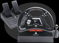
Dann's plans in a nutshell take a Playstation steering wheel, several bits of cabling and hardware to interface it, and either SNESKEY or Direct Pad Pro, and voila! Dann has allowed me to post his email address if you have questions - please don't spam him. His original MS-Word doc file to me can be downloaded - OR - here, with only minor editing (mostly cosmetic), is Dann's project!
![]()
Detachable steering wheel for your arcade control panel
![]()
In the end you end up
with a bad-ass professional looking 7 button steering with pedals that
can be taken on or off your control panel in less than a minute.
While not in use, it can be stored right inside your coin-door and the
mounted base doesnt take up hardly any space and doesnt look that bad at
all. An added bonus is that you can also hook up 2 or more(up to 5) depending
on your cabinet size. The wheels themselves look cool, are extremely durable
and have a real good feel as far as tension goes. There are 9 buttons and
1 directional pad. 2 of which are located on the rear side and are connected
to the top button on each side. The directional pad is excelent for getting
thru menus and whatever and with the extra buttons you can even add Escape
and Enter for added convenience. There is an option for an extra 2 buttons
which are inside the shifter on the original base of the wheel. The buttons
are 1/2" x 1/2" microswitches that easily pop out of their places and it
could be posible to cut the entire shifter off and somehow mount it or
install the switches inside some normal buttons but it would take some
very careful planning and techniques. The mount for the wheel is only 3"x4"
and the shaft is 1" wide and sticks out about 1 1/2". The pedals plug into
the wheel base with a 4 pin PS/2 connector so all you have to do is drill
a hole in the cabinet where you want the cable to plug in at and extend
the wire.
![]()
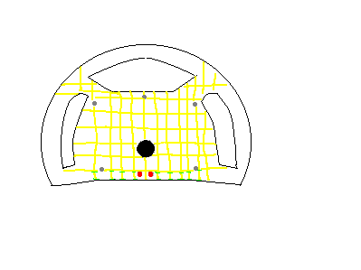
Start by removing all the screws in the base and the 3 allen bolts holding the wheel onto the base. Now carefully pop the wheel right off the base and undo the 6 screws around the mounting plate(above). Thru the center hole of the shaft (look above) run 16 small wires. Cut all of these so that there is 4" of slack for the wheel itself and then remove all the screws from the wheel and take it apart. As you are opening the wheel watch it cuz the 2 fire buttons & pads are gonna fall out. Now take the Macintosh cables and cut off 18-20"of the male ends and make sure both cables are of equal lenth. Now strip the outer casing back about 2 1/2" and then strip the small wires about 1/4" for the 2 cables and all the wires inside the wheel.
Upon inspection of the case you'll see its little "reinforcements" running like a little grid all about 2mm thick that stick out about 1/4" from the whole of the plastic (see the pictures below) you'll want to run your cables along the bottom row of these going both ways (right and left) (one for each cable) and cut the little plastic "barriers" to press the cables into place. Before attempting to install your cable you must first drill 2 holes less than a inch below the mount for the base about 3/4" apart. Use drill bits just slightly smaller than the cables and remember that the only drilling I've refered to so far should be in the back of the wheel casing. If you are attepting this you will find that each hole will end up being in the middle of the the "grid" squares. This whole grid thing may sound confusing but I ensure that if you do try this you will clearly see what I am talking about, it is very simple and I was shocked at how well, easy, and professional it all went together and looked when it was done.
Cut out the barriers just enough for the cables to press in nice and tight and then press down real hard on then and fill in each little section with hot glue ( there should be about 4 little sections on each side.). You want the cable to come around the screw posts and what I mean is thats about where the striped part should begin at(see picture above), you want the ends of the casing to stop just past where the screws go leaving about 2 1/2" of just the little wires(the ones you striped) extending up into the center of the controller. Once you've hot glued the cable into place you dont have to worry again about that cable coming loose making it safe enough to use mere small cut pieces of electrical tape to connect all the wires. Remember that ALL work mentioned so far has been for the back side of the wheel only. As you connect the wires make a chart showing what colors go to which so you dont forget later on and screw the whole thing up. Now squeeze each taped end to ensure that nothing is loose and double check everything and then carefully place the 2 fire buttons back in place and make sure no little wires are hanging out as you put the case back together. Now strip the ends of the other 2 Macintosh cables and connect them to the proper wires on the wiring harness following your little chart and mark each cable as being "1" and "2".
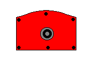
Now you can begin to remove the plate from the base. The actual mechanical part of the wheel only extends about 3 inches behind the plate and is quite compact.
To remove it from the base you must cut the plastic on each side because the tension straps are about 1/4" x 1/4" to big on each side to just simply pop the whole thing out so what you do is cut the plastic just around these to pop the thing out. Once you've removed the mechanism you must simply pop out the 2 microswitches from the shifter and the plastic base is basically junk now. Now cut the cable that the pedals pug into in half and lengthen it with whatever wire you were able to come up with (try to use the same sized wires that the cable contains) and then cut the playstation end off the interface cable. Take a small screwdriver or knife and pop the cover off the playstation connector (it literally pops right open) and jot down the wire color/pin assignments on your little chart.
Next cut you're hole(s) in your cabinet. It doesnt have to follow the same shape as the plate, it can just be a straight line across the top. Now would also be a good time to prepare any other wheels you may have decided to add. Next screw the base down into the hole. Drill out 2 holes the a little bit smaller than the 8-pin female connectors side-by-side directly underneath the plate and fasten them in there real tight and then do the same for the pedal connector. Now strip down one end of the printer cable and connect your wheel(s) as according to whichever software (SNESKEY or Direct Pad Pro --- saint) you decide to use manual's describe and add any extension cables players #2-5 if you want them to be able to plug in their controllers in the front or in the side of the cabinet. You might wanna connect the ends of the printer cable as well as the ends for the wheel to barrier strip's using the smallest type of little terminal connectors which are for connecting to telephone wires since alot of wire will go to the same pins and it will save you a mess as well as maintenance if some twisted wires lose they're connections and will also help if you decide to switch the program you use to interface with (both use different pin assignments). Doing this you will also be able to add more controllers of any type with great ease (you can have different types of controllers connected at the same time with both programs). I couldn't find any SNES exension cables anywhere so I took the piece out of an NES that the controllers usually plug into, glued the pieces together ( it falls apart when you unscrew it), cut a small square hole in the side of the cabinet and added those for players 3 & 4. Now double check all connections and fastenings.
Next get your drill back out and find a bit that fits inside of the holes that you removed the 3 allen bolts from. the one bolt normaly goes into the top and 2 in the sides straight across from each other, these 2 are the ones you want to drill, you only have to go thru about 1.5mm on each side but the plastic is high strength ABS resin and you want a clean hole. you only have to drill these 2 for whatever pin you decide to use to be able to go straight thru with ease.what i found to use is one of those "jewelers"(thats what they're called in the Radio Shack catalog) screw drivers, they have a tab on one side to pull it out with and also has grips on it that that keep it in place. if you actually go and and by these for this purpase mine came in a 3 piece set and it was the medium size one that fits perfect, it is neither loose nor tight. you could also use some sort of nail or whatever fits good.
the yellow lines are the "grid", the grey dots are the screw posts, the black dot is the mount, the red dots are the drill holes, the green dashes are where you cut
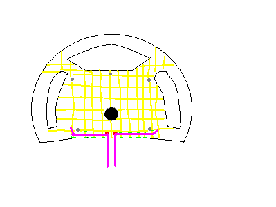
the purple lines are the cables,where they end is just where the casing covered part of the wire ends and then the 2 1/2" of striped wires go on past that.
Drill out 2 holes the a little bit smaller than the 8-pin female connectors side-by-side directly underneath the plate and fasten them in there real tight and then do the same for the pedal connector. The best way I've found to fasten them in is to use is either a piece of gas tank strap or the type of strap that brick masons use while laying block foundations. I'm not sure the actual name for it but they place it between about every 3 or 4 blocks sticking up about 12", I guess this is how they attach the wood/walls to the foundation but I know you can get it at any local hardware store for real cheap and you shouldnt need more than a foot of it. The strap is a flexable peice of steel about 3/4" wide and 1mm thick 1/4" holes about 1/4" apart. what you do is figure out how large of a piece to cut and then either cut it with tin snip's or just keep bending it back and forth till it breaks. Then run cable (the cut end)to be fastened thru it (before connecting it to whatever it gonna be connected to)and screw it into place.
![]()
Some things to take into consideration:
This is probly very pointless unless you have or intend on building you're own cabinet (which I recommend). Another thing you can do is mount the pedals on a wooden base to make them sit up higher for if you usually sit on a stool and it'd probly be best to add weight to it. Make sure you left enough slack in the 2 cables so they dont tug in the heat of action. The wheel I used is one of the original analog models. They also have a switch on them to switch between digital and analog mode for compatabilty on the playstation which should make it much more compatabile with your PC. If you do get one of these you can make up for the extra wire or 2 they may have by identifying the grounds and using the extra grounds already in the MAC cables. Other than that you should have plenty of slack left between all the other cables for your liking and could even use some to lengthen the cable that the pedals plug into. Before even hacking the thing you might wanna make sure you're gonna be able to get it to work with which ever program you decide to use by only splicing a PSX extension cable to the LPT port and connecting that to the PSX connector of the wheel.
Unless you have cabinet you built yourself chances are the coin door leaves only about 3/4" of wood underneath the control panel. Thats OK though if you if you either already plan on using 2 of them or don't mind having the wheel on the 1 player side because on both sides of the coin door there should be at least 6" which is perfect for the mount as well as space between each wheel. Many people out there have designed their control panel for only 1 player ( 1 joystick but otherwise decked out) so this probley wont look right if you are forced to mount it on either side so before you go out and buy a wheel inspect your cabinet and make sure you're gonna like the setup. Also if you do wanna have 2+ wheels only buy one first and the extension cable and make sure you can make it work before you go hacking 2+ wheels, a bunch of cables and cutting up your cabinet.
This project was invented solely by myself (Dann Jarvis) without any outside influence. Mine works fine but dont blame me if you screw yours up. You can email me at Dan420187@aol.com with any questions or comments but dont bother if you're gonna be rude. I would also apprieciate any email about any other hardware tips or breakthroughs you may have come up with. This file is not to be altered in any way but you may add things in at the end if they are of value and it actually works. (saint's note - see link to download the .doc file at top of page - if you do add to it, fire me a copy as well as Dann!)
![]()
Some links to
get you started if you're interested in building you're own cabinet:
saint's note: I
think this looks *great* - this concept is going in my vaporware dream
arcade cabinet whenever I actually get around to building the beast! :)
Thanks Dann!